Bantalan dorong mesin diesel, Ringkasan Prinsip Struktural dan Metode Penyesuaian Bantalan Dorong Mesin Diesel
Isi
Mesin utama kapal menggerakkan baling-baling melalui aksi terkoordinasi dari poros dorong, poros tengah, dan poros buritan. Ketika baling-baling berputar, baling-balingnya mengerahkan gaya melingkar dan aksial pada air. Menurut prinsip aksi dan reaksi, air juga mengerahkan gaya reaksi melingkar dan aksial yang sesuai pada baling-baling baling-baling.
Gaya melingkar yang bekerja pada baling-baling menghasilkan torsi, yang membutuhkan torsi penggerak mesin untuk mengatasi torsi yang melawan ini. Gaya aksial yang diberikan pada baling-baling sangat penting, karena gaya ini dapat menjadi daya dorong yang mendorong kapal ke depan atau tarikan yang menyebabkan kapal bergerak mundur.
Daya dorong (atau tarikan) ini ditransmisikan secara progresif: pertama melalui poros buritan, kemudian ke poros perantara, diikuti oleh poros dorong, yang akhirnya bekerja pada bantalan dorong. Bantalan dorong kemudian mentransfer gaya ke lambung kapal, mendorong kapal.
Untuk mesin diesel berkecepatan rendah menengah hingga besar yang biasa digunakan sebagai mesin utama, desain dan proses manufaktur secara khusus menyumbang bantalan daya dorong baling-baling. Biasanya, bantalan dorong dipasang pada rumah bantalan dorong di ujung buritan dasar mesin. Rumah bantalan dorong terhubung ke dasar mesin dengan dua cara: dilas atau dibaut menjadi satu unit. Fungsinya adalah untuk mentransmisikan daya dorong aksial dari poros baling-baling melalui alas ke lambung kapal, mendorong kapal ke depan.
Pada mesin diesel menengah hingga besar, bantalan dorong cincin tunggal banyak digunakan, dengan strukturnya diilustrasikan pada Gambar 1. Daya dorong menggunakan konstruksi baja tuang yang dilas dan menggabungkan dua bantalan pendukung secara internal, terutama menahan beban poros dorong dan roda gila mesin utama.
Poros dorong dibuat dari baja tuang berkualitas tinggi 35 dan terhubung ke roda gila melalui baut yang pas. Bagian tengahnya berfungsi sebagai cincin dorong, yang terhubung dengan blok dorong berbentuk kipas (5). Pengaturan ini memungkinkan gaya dorong pada poros ditransmisikan ke rumah bantalan dorong melalui blok dorong.
Blok dorong disusun dalam dua cincin konsentris: cincin depan menahan dorong selama operasi maju, sedangkan cincin belakang menangani dorong mundur. Setiap cincin dilengkapi dengan pelat penahan (7) untuk mencegah blok dorong terlepas selama pengoperasian. Blok dorong ini adalah potongan baja tersegmentasi yang terbuat dari baja karbon rendah kelas 20. Pekerja menuangkan logam putih ke permukaan kerja mereka. Logam putih tertanam melalui alur pas di bagian belakang blok dorong, sehingga memastikan pemasangan yang aman.
The bahan paduan putih yang umum digunakan adalah bantalan berbasis timah SbSnSbH-b yang mudah menyatu dengan baja karbon rendah dan menawarkan kompatibilitas yang sangat baik. Setiap permukaan dorong dilengkapi dengan delapan blok dorong untuk secara kolektif menanggung beban dorong. Shim penyangga dengan berbagai ketebalan diposisikan di belakang blok dorong. Ketika terjadi keausan, operator dapat mengganti shim untuk menyesuaikan jarak bebas aksial antara cincin dorong dan blok dorong.
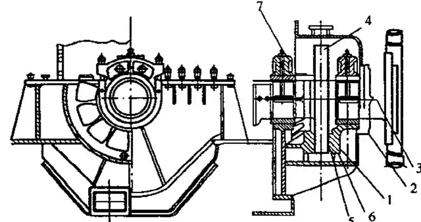
Petugas melumasi blok dorong dan cincin dorong dengan menyuntikkan oli pelumas. Bagian penyangga di bagian belakang blok dorong hanya menempati sekitar setengah dari seluruh sudut sektor. Desain ini memungkinkan blok dorong berosilasi sedikit pada tempatnya selama pengoperasian, sehingga memudahkan penetrasi oli ke permukaan kerja dan membentuk lapisan oli.
Gambar 2 mengilustrasikan konstruksi bantalan dorong untuk mesin diesel L-MC/M. Poros dorong dan poros engkol engine ini dibuat dengan menggunakan proses penempaan integral. Flensa luar cincin dorong menahan sproket penggerak untuk poros bubungan transmisi, sebuah konfigurasi yang secara efektif mengurangi dimensi aksial engine.
Bantalan dorong terutama terdiri dari blok dorong maju 8, blok dorong mundur 5, pelat dorong (cincin penyetelan) 3 dan 9, dan komponen lainnya. Delapan blok dorong maju dan delapan blok dorong mundur disusun melingkar untuk membentuk sektor yang mencakup sekitar dua pertiga lingkar.
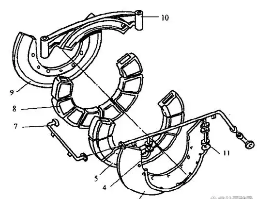
Selama operasi maju, daya dorong aksial yang dihasilkan oleh baling-baling disalurkan melalui poros buritan dan poros perantara ke cincin dorong, sehingga mendorong kapal ke depan melawan hambatan air. Untuk mencegah blok dorong berputar dengan cincin dorong, personel memasang pelacak di atas blok dorong maju dan mundur untuk penentuan posisi.
Petugas melumasi cincin dorong menggunakan oli dari utama bantalan sistem pelumasan. Untuk mencegah kebocoran oli dari jurnal di luar mesin, petugas memasang seal poros pada jurnal. Selama rotasi poros dorong, cincin pelempar oli 2 menggunakan gaya sentrifugal untuk mengeluarkan oli pelumas yang terciprat ke poros. Sisa oli dikikis oleh cincin pengikis oli.
Blok dorong adalah hal yang sangat penting komponen bantalan dorong. Meskipun strukturnya dapat bervariasi pada model mesin yang berbeda, prinsip pengoperasiannya tetap konsisten. Gambar 3 menyajikan tampilan tiga dimensi dari satu desain blok dorong. Ini mengadopsi konfigurasi berbentuk kipas. Pekerja menuang paduan putih 5 ke permukaan kerja di dekat cincin dorong dan mengerjakan fillet atau talang di tepi saluran masuk oli 2.
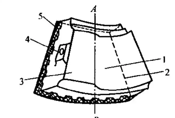
Pada sisi cincin penyetel, dua permukaan (Permukaan 1 dan Permukaan 3) dibentuk pada ketinggian yang berbeda. Tepi di mana permukaan ini berpotongan berfungsi sebagai tepi kerja selama pengoperasian, yang bersentuhan dengan permukaan kerja cincin penyetel. Kedua sisi blok dorong memiliki bos (4), yang mendukung blok dorong yang berdekatan dan membantu dalam pemosisiannya.
Dalam kondisi normal, bantalan dorong beroperasi di bawah pelumasan dinamis fluida. Lihat Gambar 4 untuk detailnya: Blok dorong 2 membelokkan sedikit di sekitar bilah penyangga, menciptakan ruang berbentuk baji di antara blok dorong dan permukaan kerja cincin dorong 3. Cincin dorong menarik oli pelumas ke dalam ruang berbentuk baji ini, sehingga menghasilkan tekanan oli yang dinamis.
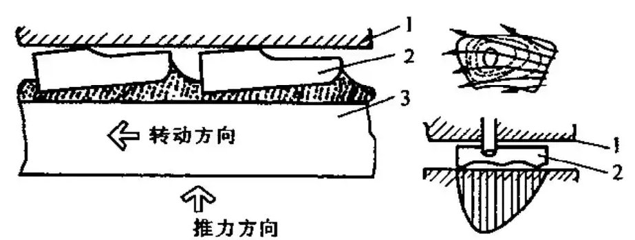
Gaya dorong yang ditanggung oleh cincin dorong disalurkan ke blok dorong melalui tekanan hidraulik, kemudian ditransfer ke cincin pengatur 3 melalui bilah penyangga. Gambar 4 juga mengilustrasikan pola aliran oli dan distribusi tekanan di seluruh permukaan kerja thrust block: Ketika daya dorong meningkat, jarak bebas antara blok dorong dan cincin dorong berkurang, meningkatkan tekanan dinamis oli dan akibatnya memperkuat daya dorong yang ditransmisikan. Sebaliknya, pada kecepatan putar yang terlalu rendah, tekanan hidraulik berkurang, yang berpotensi menyebabkan pelumasan film semi-cairan karena tekanan yang tidak mencukupi.
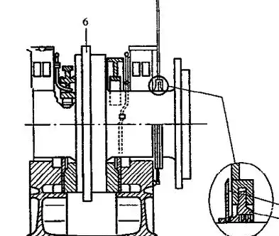
Gambar 5 menunjukkan diagram yang disederhanakan dari bantalan dorong yang khas. Blok dorong maju dan mundur diposisikan oleh pelat tekanan 6 dan 7. Ketika blok dorong ditekan bersama, celah i1 dan i2 tetap berada di pelat tekanan 6 dan 7.
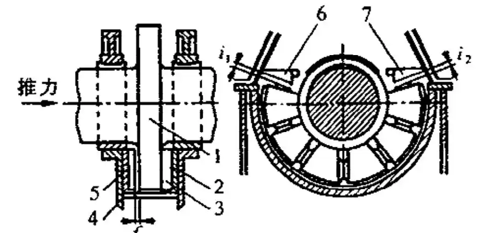
Jarak bebas gabungan i1 dan i2 harus sesuai dengan spesifikasi yang diuraikan dalam manual. Operator dapat menyesuaikan nilai spesifik dengan menambahkan atau menghapus shim di lokasi pelat tekanan. Jarak bebas ini memastikan blok dorong dapat berputar bebas di sekitar tepi penyangga, menjamin operasi bantalan dorong yang normal.
Blok dorong maju 3 bersandar pada cincin penyetelan maju 2, sedangkan blok dorong mundur 4 bersandar pada cincin penyetelan mundur 5. Cincin penyetelan ini memainkan peran penting: cincin ini tidak hanya mengatur jarak bebas antara blok dorong dan cincin dorong, tetapi juga menyetel posisi relatif aksial antara poros engkol dan bantalan.
Personil mengukur bantalan dorong jarak bebas menggunakan dua metode: Pertama, tekan dengan kuat cincin dorong ke blok dorong maju dan ukur jarak antara blok dorong mundur dan cincin dorong dengan pengukur rasa. Kedua, biarkan poros tetap dalam kondisi bebas tanpa gaya aksial, ukur celah pada cincin dorong maju dan mundur dengan pengukur feeler, kemudian tambahkan kedua pengukuran untuk mendapatkan nilai jarak bebas total.
Jarak bebas yang diukur harus memenuhi persyaratan spesifikasi. Jika tidak sesuai, teknisi harus menyesuaikan dengan menggunakan cincin penyetelan. Dalam keadaan darurat, teknisi dapat memasukkan shim sementara di belakang cincin penyetelan sebagai tindakan sementara, menggantikan cincin penyetelan selama perbaikan kapal berikutnya.
Saat memasang dua baris blok dorong di pabrik, cincin penyetelan memerlukan penyetelan khusus: Jika jarak bebas perakitan antara cincin dorong dan kedua blok dorong maju/mundur adalah 1 (2), garis tengah crankpin terakhir yang paling dekat dengan bantalan dorong harus diimbangi ke arah bantalan dorong dengan jumlah tertentu.
Hal ini mengkompensasi ekspansi termal poros engkol selama pengoperasian, yang pada akhirnya memastikan jarak bebas aksial yang seragam antara setiap lengan engkol dan bantalan utama untuk menjamin pengoperasian mesin diesel yang stabil.