Specifying Series Deep Groove Ball Bearing looks routine until the first premature failure lands on your desk. The designation on the box tells you the fit — it tells you almost nothing about whether the bearing will survive your load cycle, your temperatures and your contamination reality. This article closes that gap with the engineering logic behind the numbers.
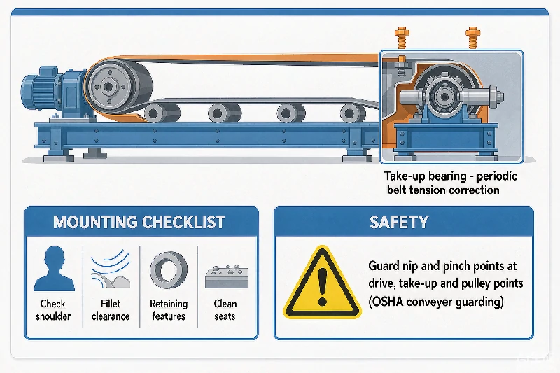
Inspect the mounting details. Check shoulders, fillet clearance, retaining features and the condition of the seats.
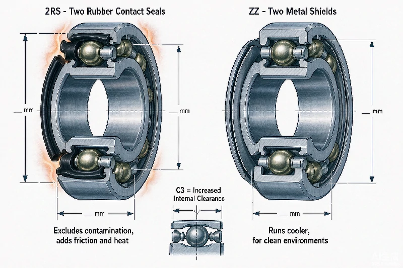
The suffix describes another part of the specification: 2RS commonly indicates two seals, ZZ or 2Z indicates two shields, and C3 identifies increased radial internal clearance.
Inhalt
Catalogs make Series Deep Groove Ball Bearing selection look like a one-number decision — match the bore and order. In practice, seven parameters interact, and changing any one of them changes the correct answer for the others. Work through them in this order and most specification errors disappear.
Two ratings are routinely confused. The dynamic load rating (Cr) is a fatigue number — the load at which 90% of identical bearings survive one million revolutions. The static load rating (C0r) is a deformation number — the load that produces a permissible permanent dent at the contact points. Sizing a slow or oscillating application from Cr, or a rotating application from C0r, are both classic mistakes.
Internal clearance shrinks in service: interference fits remove some, and thermal expansion of the inner ring removes more. Choose the class so the residual operating clearance stays positive but small.
| Clearance class | Typical application | Risk if misused |
|---|---|---|
| C2 (tight) | Precision spindles, minimal play | Risk of seizure if hot |
| C0 (Normal) | General industrial machinery | Default choice |
| C3 | High temperature, interference fits both rings | Most common upgrade |
| C4 | Very hot or high-vibration service | Vibrating screens, kilns |
A common sizing error: choosing a bearing by bore diameter alone and assuming any bearing in that bore size will do. At an identical bore, moving up one series can nearly double the dynamic load rating — the gap between series is exactly where undersized replacements get ordered.
Material selection sets the ceiling on Series Deep Groove Ball Bearing performance before any sizing math begins. The operating environment — temperature, moisture, contamination and speed — determines which combination of raceway material, rolling elements, cage and seals will survive. Most premature failures attributed to ‘bad bearings‘ are actually material mismatches.
The table below summarizes the practical envelope of the four most common material systems. The right choice is almost always dictated by the two harshest conditions in the application, not the average conditions.
| Material system | Used for | Typical envelope |
|---|---|---|
| 52100 chrome steel | Standard raceways and rolling elements | General industrial duty, −30 to 120°C |
| 440C stainless steel | Corrosion-resistant raceways and balls | Food, marine, chemical and washdown duty |
| Si3N4 ceramic (hybrid) | Rolling elements only | High speed, high temperature, electrical insulation |
| Full ceramic (Si3N4/ZrO2) | Raceways and rolling elements | Extreme temperature, non-magnetic, corrosive media |
| M50 tool steel | Raceways and rolling elements | Aerospace and high-temperature specialty duty |
The cage (retainer) keeps rolling elements evenly spaced and prevents skewing. Its failure is catastrophic because it usually destroys the rest of the bearing within minutes. Match the cage to the failure mode you are guarding against, not to the price list.
| Cage type | Strengths | Limitations |
|---|---|---|
| Pressed steel | Shock load tolerance, general duty | Standard operating temperatures |
| Machined brass | Quiet running, high speed | Higher cost, limited availability |
| Polyamide (nylon 66) | Low friction, low noise | Limited to −40 to 120°C |
| Phenolic resin | High-speed spindles | Oil lubrication preferred |
Seals deserve the same rigor. Contact seals (2RS-type) exclude contamination but add friction and heat; non-contact shields (ZZ-type) run cooler but assume a clean environment. In dusty or wet service, the sealing decision frequently matters more than the bearing series itself.
Industry field studies consistently attribute over a third of premature Series Deep Groove Ball Bearing failures to lubrication problems — wrong type, wrong amount, wrong interval, or contamination. The lubricant is a machine element, not a consumable afterthought.
| Lubrication method | Best suited for | Critical note |
|---|---|---|
| Grease (lithium complex) | Sealed or hard-to-service positions | Fill 30–50% of free volume |
| Circulating oil / oil bath | High temperature, gearboxes | Level at center of lowest rolling element |
| Oil mist / air-oil | High speed (>60% of limiting speed) | Precise metering, minimal drag |
| Solid / dry film (MoS2) | Extreme heat, vacuum | Limited Tragfähigkeit |
Quantity matters as much as type. Over-greasing causes churning: the rolling elements plow through excess grease, temperature climbs 20–40°C, oxidation accelerates, and the grease’s base oil separates. As a field rule, fill 30–50% of the free internal volume for general duty, and nearer 30% for high speed.
Never mix grease thickener families (lithium with calcium sulfonate, for example) without verifying compatibility — incompatible mixtures can soften and leak out within weeks. When in doubt, purge completely and refill with the new product.
The mounting process defines certain constraints, including available space, installation sequence, and the potential need for lifting equipment. Ensure these constraints align with the requirements of your mounted bearing solution. Key considerations include:
When reading a drawing, trace the load line from the rolling element toward the raceways and ask:
Take-up bearings show up on belt conveyors, bucket elevators, drag chain conveyors, and overhung shaft drives — anywhere tension needs periodic correction. Nip and pinch points at these tensioning locations are also a recognized workplace hazard on conveyor systems; OSHA’s guidance on conveyor guarding covers what needs to stay shielded during operation, including drive, take-up, and pulley points.
Cons: Can damage the shaft (scarring); slightly pushes the shaft off-center, which can cause vibration at high speeds.
For standard metric bearings, multiply the two-digit bore code by five to get the bore in millimeters — a 15 code means a 75 mm bore. Exceptions exist for codes 00–03 (10, 12, 15 and 17 mm respectively) and for bearings designated directly by dimension.
Fit dimensions — bore, OD and width — are ISO-standardized, so they interchange mechanically. Load ratings, clearance and internal geometry differ between manufacturers, so verify that the substitute’s published dynamic load rating matches or exceeds the original before installation.
Reference speed is a thermal rating — the speed at which heat generation equals dissipation under standardized conditions. Limiting speed is a mechanical ceiling set by cage strength and lubricant retention. For continuous duty, size against the reference speed; the limiting speed is not a safe continuous rating.
No. Suffixes change internal clearance (C3/C4), bore profile (K = tapered) or lubrication features (W33 = groove and holes in the outer ring) — the boundary dimensions of bore, OD and width stay identical to the base designation.
Series differ in width, Außendurchmesser and internal geometry. A wider series carries longer rollers or larger balls, which raises the dynamic load rating — sometimes by 70% or more at the same bore.
The pattern across every section of this guide is the same: the expensive Series Deep Groove Ball Bearing problems are decided early, quietly, at specification and installation. The cheap time to fix them is now, with the tables and procedures above — not after the line stops.
Shanghai Furuisheng Precision Bearing Co., Ltd. engineers and supplies precision bearing solutions for industrial customers worldwide — from standard deep-groove and spherical roller bearings to application-specific designs in stainless, hybrid ceramic and high-temperature configurations. If your project involves Series Deep Groove Ball Bearing, send us your operating conditions and drawings; our engineering team will return a sizing recommendation and quotation within one business day.
 English English
 العربية
 Deutsch (Sie)
 Español
 Français
 Bahasa Indonesia
 Italiano
 日本語
 Português
 Русский
 Türkçe
 简体中文
 Nederlands (Formeel)
 Svenska
